Complete reference for flashing firmware to Solterra charger units.
Two upgrade paths are available: Method B (CAN Bus) uses a USB CAN
Analyzer and requires AC mains power applied after trigger — this is
the default OEM workflow with lower complexity. Method A (TTL Serial)
uses a USB–TTL UART adapter with AC mains disconnected and requires
physical access to the PCB 6-pin header — use this for virgin units,
bricked units, or when CAN is not available. Both methods use
DownloadTool v2.00.00 (no installation required).
The CAN upgrade method only works if the charger already has CAN
communication capability loaded. A charger without existing
functional CAN firmware cannot be upgraded via CAN — use Method A
(TTL) for virgin or bricked units.
Bench Reference Tip
Build the session first, power the charger second
The fastest flash sessions happen when your team stages the tool,
IDs, baud, and firmware file before the charger ever sees power.
Host tool
DownloadTool v2.00.00
86 KB standalone executable — no installation required, double-click to run on Windows.
Default interface
CAN Bus
Use CAN first (lower complexity) for OEM benches, validation stations, and production-style flashing. Requires charger with existing CAN firmware.
Fallback interface
TTL Serial
Use TTL (moderate complexity) for virgin units, bricked units, or when CAN programming is not available. Requires physical access to PCB 6-pin header.
Critical voltage
⚠ 3.3V Only
The charger UART port operates at 3.3V logic level. Using a 5V TTL device will damage the charger MCU permanently.
Typical OEM Jobs
Why you would open this page
This guide is written for a bench engineer, validation lead, line
technician, or service technician who needs a clean flashing workflow
instead of a document dump.
OEM Use Case
Bench validation
Check bootloader access, prove a firmware build, and confirm the right interface before release.
OEM Use Case
Production flashing
Use the CAN path when you want the cleanest line-side workflow without opening the charger.
OEM Use Case
Service recovery
Move to UART only when CAN is unavailable or you need direct board access on the bench.
Preflight
Set the session up before you flash anything
Checklist
Before you connect the first charger
Confirm charger revision and target .hex file before you connect any tool.
Lock the exact CAN TX/RX IDs and baud rate for the session before you energize the charger.
Keep AC mains disconnected until the CAN power-on step or throughout the full UART / TTL flow.
For CAN: verify the charger already has CAN communication capability in its firmware. A charger without existing functional CAN firmware cannot be upgraded via CAN — use TTL for virgin or bricked units.
For TTL: verify the USB–TTL converter operates at 3.3V logic level. Using a 5V TTL device will damage the charger MCU.
Record serial number, firmware file, and pass/fail result for traceability.
Route Selection
Choose the right path once
Method B — CAN Bus (lower complexity)
Default OEM workflow. Interface: USB → CAN Analyzer. Charger AC mains required (applied after trigger). Prerequisite: charger must already have CAN communication capability in firmware.
Method A — TTL Serial (moderate complexity)
Fallback for virgin, bricked, or CAN-incapable units. Interface: USB → TTL UART. Charger AC mains must be disconnected. Prerequisite: physical access to PCB 6-pin header (J208 / MARK3).
Stop if session data is unclear
Wrong .hex file, baud rate, or CAN IDs waste more time than the flash itself. Lock all values before you energize.
Primary Workflow
CAN tool based programming
Start here when the charger already supports CAN programming. This is
the closest match to a clean OEM bench or line workflow because you
stay on the harness and avoid opening the charger.
CAN Step 01
Start with the right CAN hardware
Use CAN only when the charger build already has CAN communication capability loaded in its firmware. A charger without existing functional CAN firmware cannot be upgraded via CAN — use Method A (TTL) for virgin or bricked units.
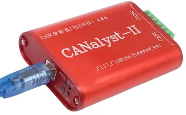
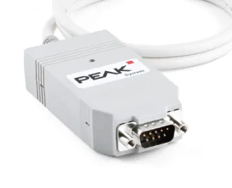
CAN Analyzer — supported models: Chuangxin Technology CANalyst-II (red metal enclosure, USB CAN analyzer) or PEAK System PCAN-USB (grey USB dongle with DE-9 connector).
CAN cable — 2-wire twisted pair carrying CANH and CANL lines only. Match polarity end to end before you open the tool.
Termination — add a 120Ω resistor between CANH and CANL if the charger does NOT have built-in 120Ω termination.
Firmware file — .hex format image for the target charger revision.
Keep AC mains off until the update step — power is applied after the trigger.
CAN method prerequisite: the CAN upgrade only works if the charger already has CAN communication capability loaded. If it does not, do not keep chasing CAN errors — use Method A (TTL) for virgin or bricked units.
CANalyst-II — Chuangxin Technology USB CAN analyzer (red metal enclosure). Use when your bench is built around Chuangxin tooling.PEAK CAN — PEAK System PCAN-USB (grey USB dongle with DE-9 connector). Use when that is your standard OEM debug adapter.
CAN Step 02
Put DownloadTool in CAN mode
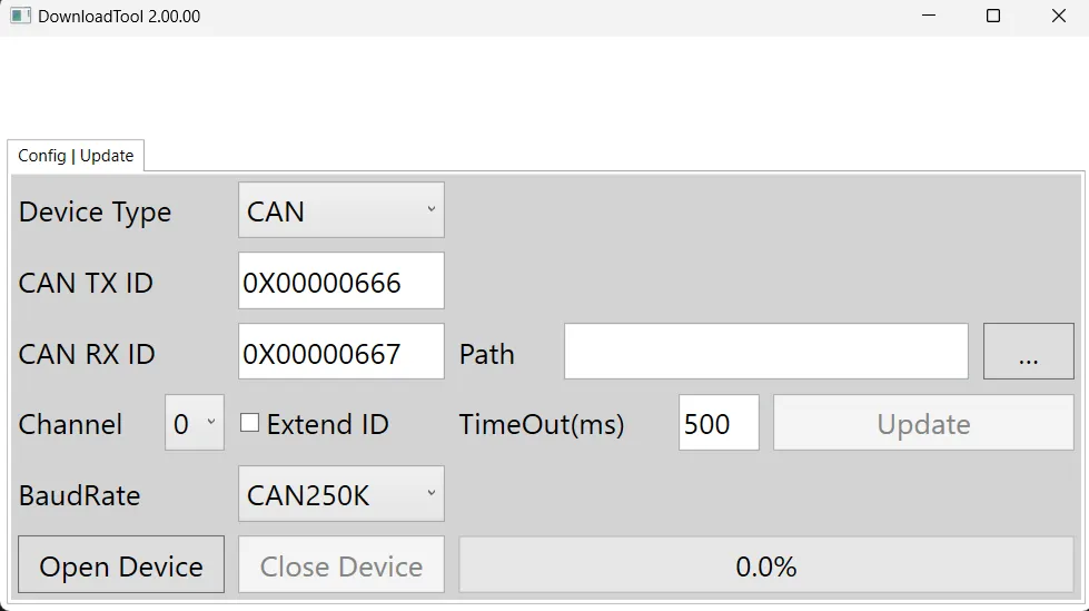
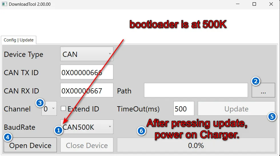
Launch "DownloadTool.exe", set Device Type to CAN, and keep Channel on 0 unless your driver setup says otherwise.
Use the clean CAN screen as your baseline before you enter project values.
Do not power the charger until the session is staged.
Keep the firmware path empty until you know the exact build you want to flash.
Use this baseline CAN screen before you enter IDs, baud, and firmware path.
CAN Step 03
Set IDs, baud, and the .hex file
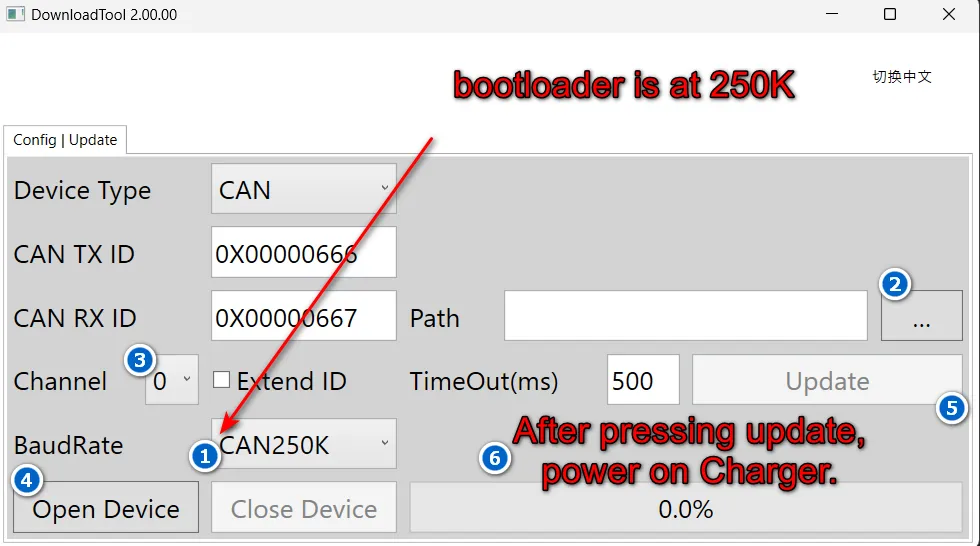
Load the correct .hex firmware file, set the right CAN TX and RX IDs, and match the bootloader baud rate before you open the device.
UI field — CAN TX ID: set to 0X00000666 (recovered reference value).
UI field — CAN RX ID: set to 0X00000667 (recovered reference value).
Baud rate detection — start with the project baud if known. If unknown, try 250K first, then 500K, then 125K in order. The correct baud must match the charger bootloader.
Browse and load the target .hex firmware file into the DownloadTool file path.
Do not click "Open Device" until all three values — TX ID, RX ID, and baud rate — match the charger in front of you.
Baud rate detection: if you do not know the charger baud, try each standard rate (250K → 500K → 125K) one at a time with a full power-on cycle between each attempt. For OEM teams handling multiple variants, label the .hex file and CAN profile before the charger sees power.
250K baud rate — the safest first try when you do not already have a known-good project baud.500K baud rate — use this profile when your charger build calls for the faster bootloader setting.
CAN Step 04
Flash inside the power-on window
Click "Open Device", then click "Update". Immediately apply AC mains power to the charger within roughly two seconds so the bootloader catches the programming request during its startup window.
Verify all session values are final (TX ID, RX ID, baud rate, .hex file) before clicking "Update".
Apply AC mains power to the charger within the 2-second timing window after clicking Update.
The charger bootloader only listens for a CAN programming request during the first moments after power-on.
Wait for the success message in DownloadTool before disconnecting the charger or removing power.
Treat the power-on timing window as the main CAN flash checkpoint. Good wiring and correct IDs alone are not enough if the AC mains power is applied outside the ∼2-second bootloader window.
CAN Step 05
Troubleshoot CAN failures methodically
When CAN flashing fails, change one variable at a time so you can isolate the fault quickly. Follow this exact diagnostic order.
Step 1 — Recheck CANH and CANL polarity. Swapped lines are the most common wiring fault.
Step 2 — Add 120Ω termination between CANH and CANL if the charger side does not already provide built-in termination.
Step 3 — Retry alternate baud rates one by one (250K → 500K → 125K) with a full power-off/power-on cycle between each attempt.
Step 4 — Repeat the same 2-second power-on sequence for each controlled retry. Do not change multiple variables at once.
Step 5 — Ensure the Extend ID checkbox is unchecked. The bootloader uses standard 11-bit IDs.
If all CAN attempts fail, the charger may not have CAN communication capability in its firmware — switch to Method A (TTL Serial).
Do not random-retry CAN flashes. On an OEM bench, work the problem in this exact order: (1) wiring polarity, (2) 120Ω termination, (3) baud rate, (4) power-on timing. If all fail, the charger may need TTL recovery.
Fallback Workflow
UART tool based programming
Use UART when you need direct board access, when CAN flashing is not
exposed on the charger build in front of you, or when you are
recovering a unit on the bench after the CAN path fails.
UART Step 01
Prepare the UART toolchain first
When you need direct board access, gather the required hardware and software, install the driver, unpack the host tool, and keep the executable ready before you touch the charger header.
USB–TTL Converter — must be an isolated USB to TTL serial port tool supporting 3.3V logic level. DO NOT use 5V TTL — hardware damage will result.
Jumper / header cable — 4-wire dupont-type for VCC, GND, TXD, RXD connections to the charger 6-pin header.
Install driver software "CDM20828_Setup.exe" — FTDI VCP driver (1,870 KB, dated 2018-09-12). This exposes a stable COM port for your UART adapter.
Firmware file — the target .hex format firmware image to be flashed.
PC access — Windows with COM port number verified via Device Manager → Ports.
Unzip "DownloadTool_V2.00.00.zip" and run "DownloadTool.exe" (86 KB, no installation required — double-click to run).
CDM20828_Setup.exe — FTDI VCP driver (1,870 KB). Install first so Windows exposes a stable COM port for your USB–TTL adapter.DownloadTool_V2.00.00.zip — unpack the host tool archive before you wire the charger.DownloadTool.exe — 86 KB, no installation required. Double-click to run for the UART flash session.
UART Step 02
Wire 3.3V UART with AC disconnected
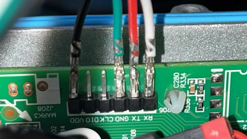
Open the charger bottom plate to access the 6-pin PCB header (silkscreened J208 / MARK3). This is the UART programming port. Keep AC mains disconnected throughout the entire TTL procedure.
Leave AC mains disconnected — charger power is not required during TTL flashing.
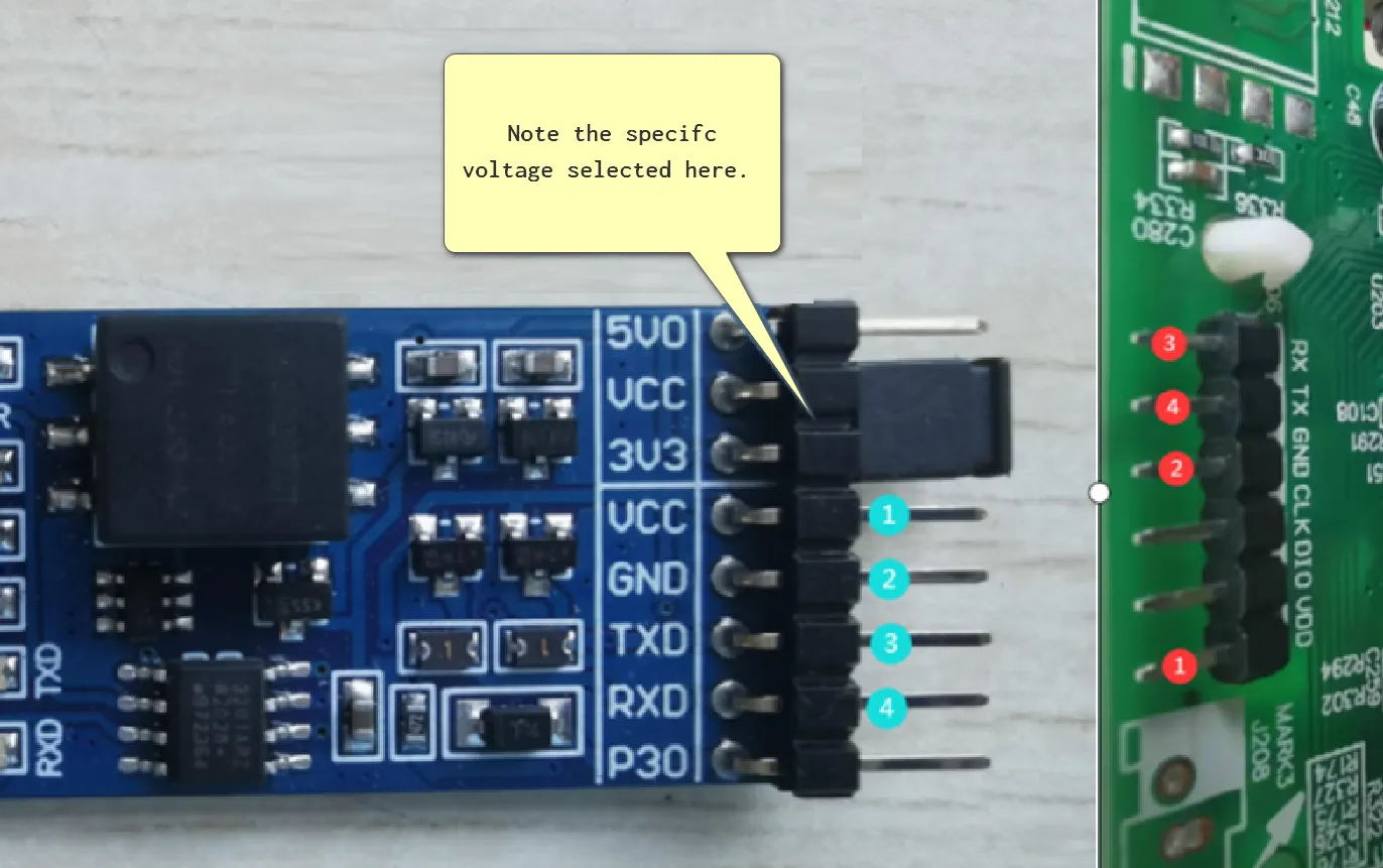
Charger 6-pin header pinout (from board silkscreen, right-to-left): RX · TX · GND · CLK · DIO · VDD. Only 4 of 6 pins are used — CLK and DIO are NOT connected during this procedure.
Wire ① — Adapter VCC (3V3 jumpered to VCC) → Charger VDD. ⚠ MUST be 3.3V.
Wire ② — Adapter GND → Charger GND (ground reference).
Pin order varies by adapter — different USB–TTL adapters have different physical pin orderings. Always verify by reading the PCB silkscreen on your specific adapter before connecting.
Critical: 3.3V logic level only. The charger UART port operates at 3.3V logic level. Using a 5V TTL UART device will damage the charger MCU. On multi-voltage USB–TTL adapters, physically jumper the VCC selector to 3.3V / 3V3 before connecting. If building a fixture, lock the voltage selection physically.
Use this pin map to confirm 3.3V voltage selection (jumper must bridge 3V3 and VCC, NOT 5V0 and VCC) and the crossed TX/RX wire order.Charger 6-pin header (J208 / MARK3) close-up — verify RX, TX, GND, and VDD positions on the charger PCB before connecting.
UART Step 03
Set Serial Port mode and pick the right COM port
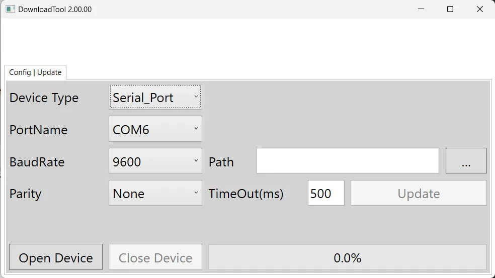
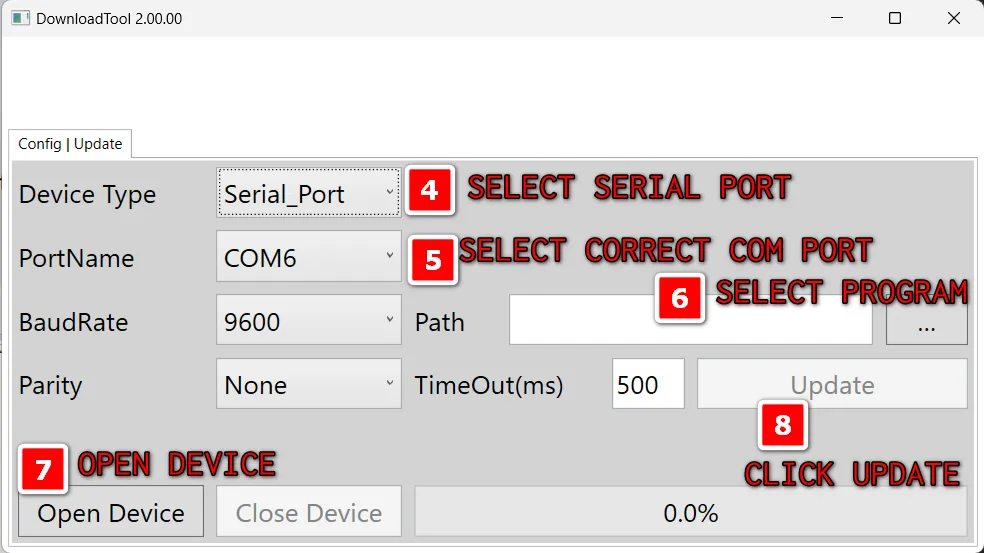
Launch DownloadTool.exe, switch Device Type to "Serial_Port", choose the COM port exposed by your USB–TTL adapter (verify via Device Manager → Ports), and then stage the .hex firmware file.
UI field — Device Type: select "Serial_Port" from the dropdown.
UI field — COM Port: pick the COM port number assigned to your USB–TTL adapter. Verify via Device Manager → Ports (COM & LPT).
UI field — BaudRate: set to 9600 (default serial baud for the UART bootloader).
UI field — Parity: set to None.
Browse and load the target .hex firmware file path.
Click "Open Device" to establish the serial connection, then click "Update" to begin the firmware flash.
DownloadTool in Serial_Port mode — use this baseline screen before you select the COM port, set BaudRate to 9600, Parity to None, and load the firmware file.Annotated screen showing COM port selection, BaudRate 9600, Parity None, firmware file path, and the Open Device / Update actions.
UART Step 04
Recover from handshake failures in order
A stalled UART session usually comes down to the COM port assignment, crossed TX/RX lines, incorrect voltage level, or VCC timing during the handshake sequence.
Recheck the COM port number in Device Manager → Ports (COM & LPT) first — adapters can reassign on replug.
Verify TX and RX are crossed exactly once (adapter TXD → charger RX, adapter RXD → charger TX).
Confirm the USB–TTL adapter is jumpered to 3.3V / 3V3, not 5V — a 5V connection will damage the MCU.
Verify CLK and DIO pins on the charger header are NOT connected — only VDD, GND, TX, and RX are used.
After you press "Update", if the host tool shows "Handshake in progress" without completing, unplug and replug the VCC lead from the charger header to reset the bootloader handshake.
Keep AC mains disconnected throughout the entire UART recovery procedure.
If you see "Handshake failed" or "Handshake in progress", work the problem in this exact order: (1) COM port assignment, (2) TX/RX crossing, (3) 3.3V voltage level, (4) VCC replug timing. Do not skip steps.
Files
Download the approved tool archives
Hand your operators the exact ZIP that matches the CAN adapter,
host-tool revision, or Windows dependency your bench standard
requires.
CAN Driver Pack
Canalyst drivers.zip
Use this driver bundle when your CAN bench is built around CANALYST hardware.
Keep one approved ZIP set per charger release or service program. That
avoids benches drifting onto mismatched host-tool builds.
Inventory
File Inventory
Reference table of exact software and firmware files for the flashing
process.
Filename
Size
Date
Purpose
Method
DownloadTool_V2.00.00.zip
—
—
Distribution archive — extract before use
Both
DownloadTool.exe
86 KB
2023-12-26 08:11
Main firmware flashing application (portable, no install)
Both
CDM20828_Setup.exe
1,870 KB
2018-09-12 18:07
FTDI VCP USB serial driver installer
TTL only
<firmware>.hex
Varies
—
Intel HEX firmware image to be flashed
Both
Hardware Reference
Charger 6-Pin Header
Located on the charger PCB, accessible by opening the bottom plate.
Silkscreened as J208 and MARK3.
Physical Position
Silkscreen Label
Function
Used for Firmware Upgrade
Pin 1
VDD
3.3V supply / reference
✅ Connect to adapter VCC (3.3V only)
Pin 2
GND
Ground
✅ Connect to adapter GND
Pin 3
TX
UART Transmit (charger → host)
✅ Connect to adapter RXD
Pin 4
RX
UART Receive (host → charger)
✅ Connect to adapter TXD
Pin 5
DIO
Debug/programming data
❌ Not used for DownloadTool
Pin 6
CLK
Debug/programming clock
❌ Not used for DownloadTool
Pin numbering orientation: The silkscreen reads RX TX GND CLK DIO VDD when the board is oriented with the header at top-right (component-side
up). The numbering in the table above reflects physical pin 1 = VDD.
Diagnostics
Error Reference
Error Message
Method
Root Cause
Resolution
Handshake failed
Both
No valid bootloader response received within timeout
Check wiring (TTL) or baud rate & timing (CAN). See troubleshooting sections.
Handshake in progress
Both
Tool is attempting to establish bootloader handshake but has not yet received ACK
For TTL: replug VCC to power cycle the MCU. For CAN: ensure AC power is applied within 2 seconds of clicking Update.
Internal Links
Keep the Programming Context Nearby
Keep moving between the support guides below to narrow the issue faster.